
IF Tap Panadapter Board

Hi-Z IF Tap Board
See the eHam reviews at: https://www.eham.net/reviews/detail/13865
The PAT (Panoramic Adapter Tap) Panadapter Hi-z tap board circuit was designed by the late Dave Powis, G4HUP/SK.
The circuit is designed to provide a convenient method of adding a “RX Output” and/or “IF Output” to your existing rig by tapping off the RF or IF of your receiver or transceiver so that it can be displayed panoramically via an SDR. Its purpose is to present a high impedance to the RF or IF circuit and therefore minimize any loading on the main signal path of the radio. It will work in just about any solid state radio transceiver or receiver.
With the PAT board installed in the target rig, the output can be routed out via a chasis mounted SMA, RCA or BNC connector or via a cable pigtail, through the rear panel. The PCB is small enough to fit inside a modern all-band portable rig and can conveniently be ‘lost’ inside base-station rigs. The board dimensions are approximately 1” x 1.6”
Radios with 1st IF’s up to 250MHz and as low as 455KHz can be accommodated by the PAT IF board with a change of the low pass filter (LPF) on the output. It is preferable that the input to the PAT is tapped off the input to the 1st IF filter to give the maximum displayed bandwidth on the SDR. Customized low pass filters are available upon request. The PAT V board has no low pass filter and is designed to tap the RF of your receiver or transceiver.
Power for the PAT is taken from inside the existing rig, preferably from a switched 8 – 13.8 VDC Rx supply. The circuit draws approximately 11mA from the host rig. Since the 1st IF filter of many transceivers are bidirectional and is used on both Tx and Rx, it is recommended that the PAT voltage supply (Vcc) be taken from a switched supply which is ‘on’ during Rx and ‘off’ during TX. This avoids any strong TX path signals being presented to the SDR during TX periods. In base station rigs the +RxB is typically 8 - 12VDC. However, any PAT model can be built to operate at 5 VDC upon request.
Circuit Description
The PAT Board is a buffer with a unity gain amplifier that has two active stages, a JFET source follower to present a high impedance to the IF circuit and therefore minimize any loading on the main signal path of the radio. This is followed by a BJT as an emitter follower to provide impedance transformation for a following filter stage.
The two passive stages that follow are a 50 ohm low pass filter to limit the passage of signals above the IF, and a resistive attenuator to allow the overall gain of the board to be matched to the input requirements of the SDR. Attenuation can be added to the PAT board output based on your SDR’s requirements, but installing an external attenuator is recommended.
Installation
Installation instructions are available for most rigs. If not, I will try to provide you with the recommended tap points for the IF and power if requested. (Click on the "Rig List & Links" button at the bottom of the page.)
RF Tap Panadapter Board & Ordering Information
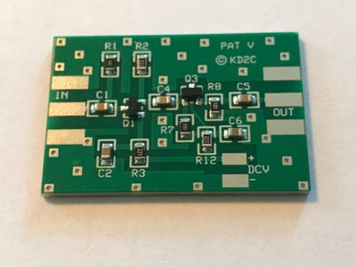
The PAT V RF Tap Board
This version has no LPF installed, it is therefore ideally suited to 2nd Rx functions. It can be installed in all the radios posted in the rig list including the Yaesu 817/847/857 and 897 series. These
radios all use a common 1st IF, which means that picking up the tap point just before the first
mixer gives you access to the RF signal on all bands that the radio covers. This is more difficult
on those radios that do not use a common 1st IF, such as the Kenwood and Icom all band
offerings. The PAT V board is also ideally suited for HF rigs.
PAT V - Second Receiver Function
In addition to giving you a panoramic display centered on your Rx tuning, the PAT V can be used to give a wider view as an independent second Rx. The input signal for the PAT V needs to be picked up before the 1st mixer, and your SDR must be tuned to the frequency/band you are receiving, instead of the IF frequency of your radio. Operation is different, in that the SDR display will no longer change as you tune the band on your rig, it will remain fixed unless your SDR software has rig control. The PAT V will work
in just about any solid state and direct sampling rigs including the IC-7300 and FTdx-10.
Installation
IMPORTANT: Installing the PAT board is not for the novice or beginners. If you don’t feel comfortable doing it yourself, have it installed by someone who is.
Installation instructions are available for most rigs. If not, I will try to provide you with the recommended tap points for IF/RF and power if requested. (Click on the "Rig List & Links" button at the bottom of the page.)
Ordering Information
All versions of the board are available. Each assembled board is made to order based on your rigs specific IF requirements.
The cost for the IF and RF tap board is $22 per board plus shipping.
A "Connection Kit" is available for $7, this includes:
15 in. – RG 178 Output Cable
15 in. – Red & Black 26 AWG Power Connection Wires
7 in. – 30 AWG IF Tap Wire.
1 – SMA Pigtail or SMA, BNC or RCA Female Panel Connector (PLEASE SPECIFY WHEN ORDERING)
(Add $7 for SMA Pigtail)
1 – 1x2 Strip of Double Sided 3M Foam Tape
SMA-RG-316 cables are available. Please see the "Cables" page for details.
All orders are shipped via USPS 1st Class Mail. Domestic orders over $100 are upgraded to USPS Priority Mail at no additional charge.
Shipping:
US: $8 - $12
Canada & Mexico: $18 - $26
Europe, Asia & anywhere else: $20-$28 (For 6 Boards or 3 Boards & 3 Connection Kits)
PAYMENT IS ACCEPTED VIA PAYPAL TO: kd2c56@gmail.com